PDS
Plastic Deformation Sensor (PDS) is a unique solution, that allows for unambiguous identification of the plasticisation moment of the monitored material.
Plastic Deformation Sensor (PDS) is a unique solution, that allows the unambiguous identification of the plasticisation moment of the monitored material, without the need to know its characteristics (in particular the sigma-epsilon curve), its initial stress state and its current technical condition.
Plastic Deformation Sensor (PDS) is a unique solution, that allows the unambiguous identification of the plasticisation moment of the monitored material, without the need to know its characteristics (in particular the sigma-epsilon curve), its initial stress state and its current technical condition.
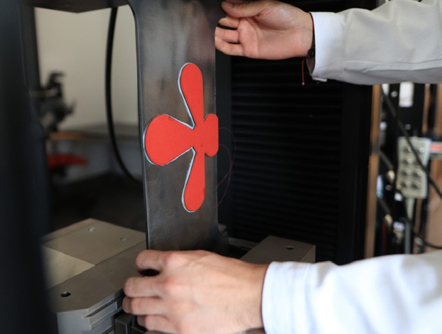
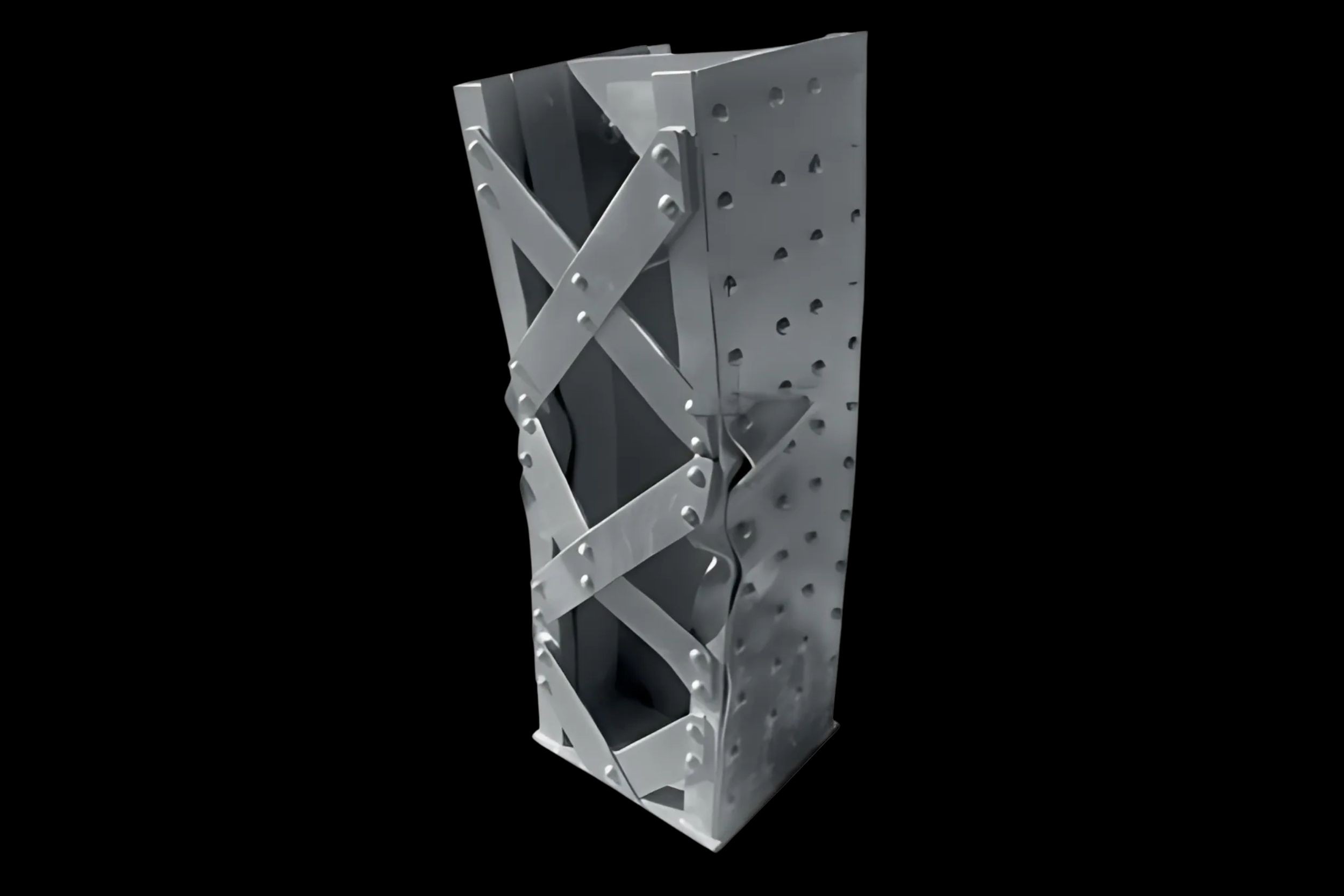
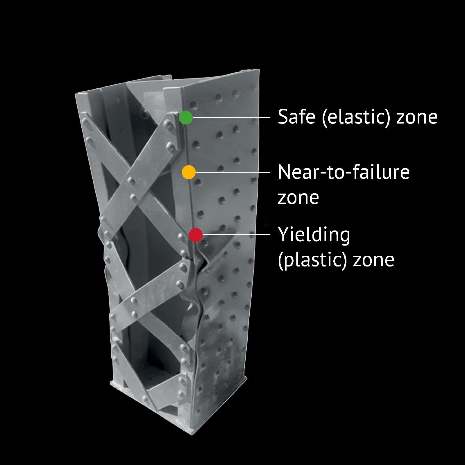
The sensor consists of appropriately configured measuring elements (e.g. strain gauges, spot sensors, FBG gratings or DFOS optical fibres). The measurements cover selected areas of the structure that are safety-critical due to the risk of stress extremes. Measurements are taken automatically at a pre-set frequency over time and an early warning system alerts about any irregularities.

PDS Advantages
Physical Quantities Measured
Yield detection
Typical Materials
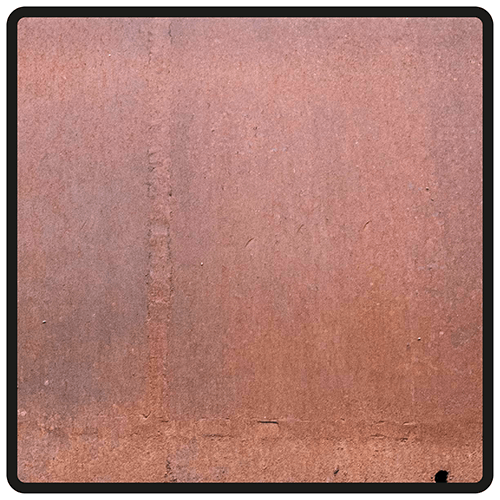
Steel
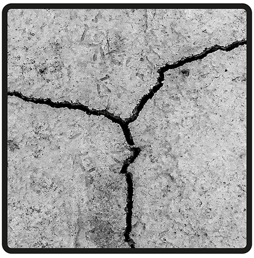
Concrete
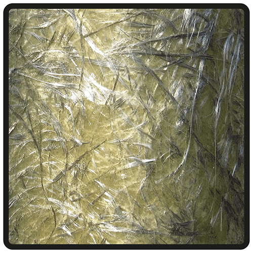
Composite
PDS Application Areas
Structures | Bridges | Piles | Slurry walls | Pipelines | Tunnels | Railways | Laboratories… and more
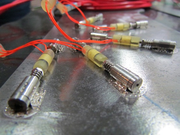
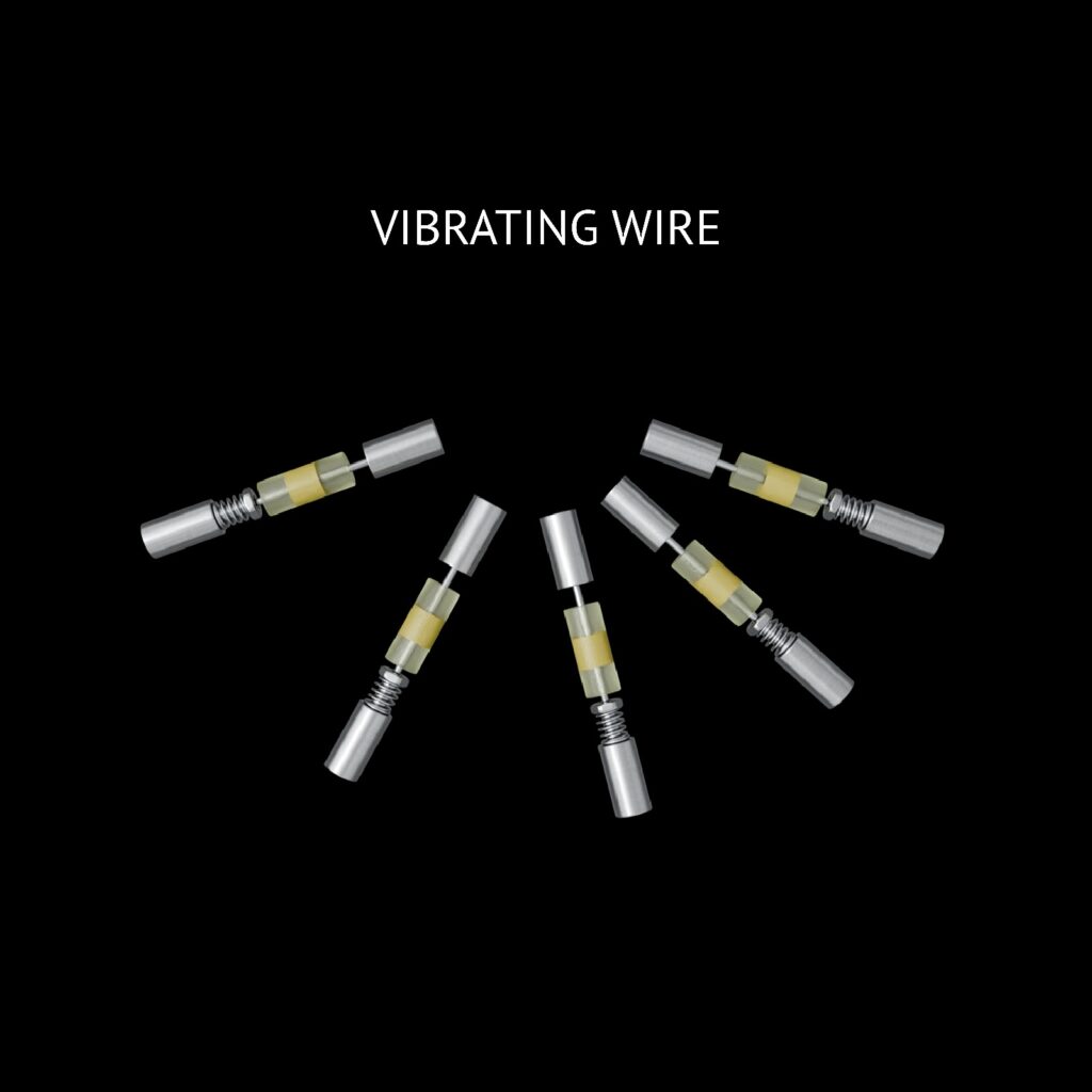
Plastic deformation sensors in vibrating wire technology
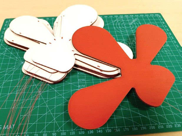
Plastic deformation sensors in foil strain gauge technology
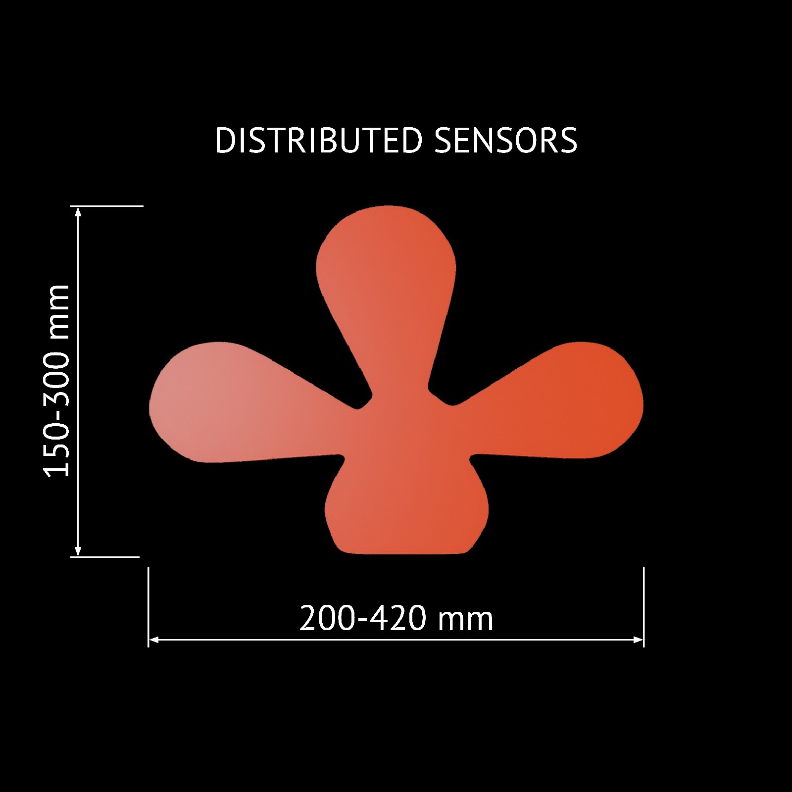
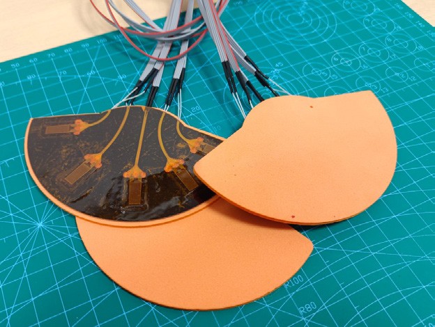
Plastic deformation sensors in optical fibre technology (DFOS or FBG)
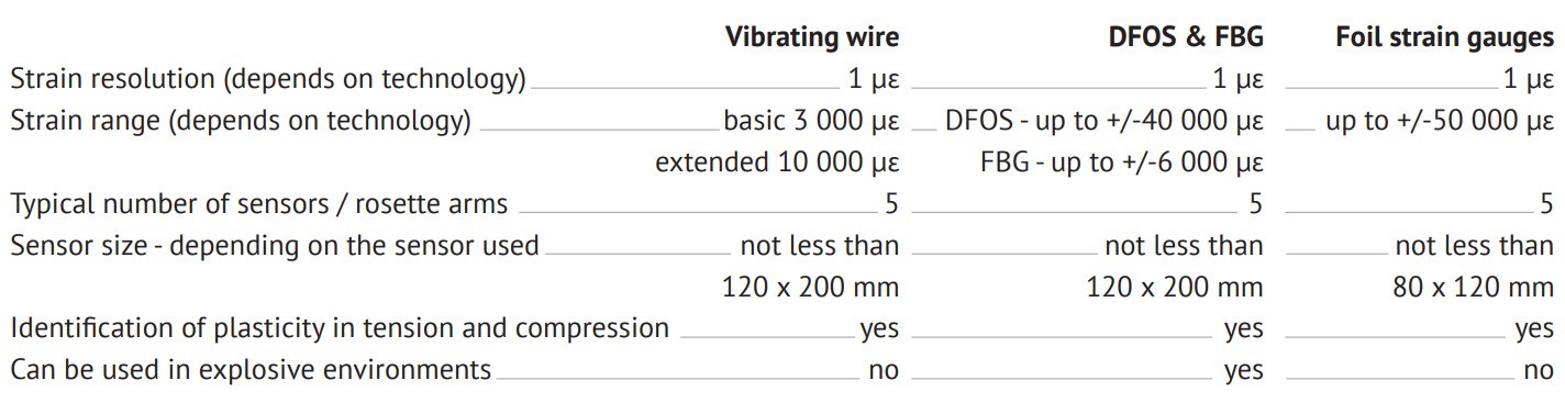
PDS Technical Specifications
Vibrating wire
DFOS & FBG
Foil strain gauges
Strain resolution
(depends on technology)
1 μɛ
.
1 μɛ
.
1 μɛ
Strain range
(depends on technology)
basic 3 000 μɛ
extended 10 000 μɛ
.
DFOS – up to +/-40 000 μɛ
FBG – up to +/-6 000 μɛ
.
up to +/-50 000 μɛ
–
Typical number of
sensors / rosette arms
5
.
5
.
5
Sensor size – depending
on the sensor used
not less than
120 x 200 mm
.
not less than
120 x 200 mm
.
not less than
80 x 120 mm
Identification of plasticity
in tension and compression
yes
.
yes
.
yes
Can be used in
explosive environments
no
.
yes
.
no
PDS Technical Specifications
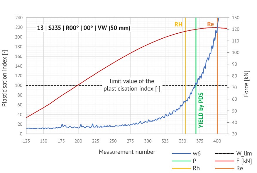
Tensile Test Result
The red line is the curve obtained from the universal testing machine (right vertical axis). It shows the time dependence of the force (increase in force over time represented as a measurement number). The vertical lines indicate the time moments at which the force reached the proportional limit (Rh) and yield strength (Re).
The green line marks the moment at which the PDS sensor detected plasticisation. From the tests, we determined the value of the plasticisation index (left vertical axis) at which plasticisation of the material definitely occurs (in this case,
a value of 100).
The green line marks the moment at which the PDS sensor detected plasticisation. From the tests, we determined the value of the plasticisation index (left vertical axis) at which plasticisation of the material definitely occurs (in this case,
a value of 100).
2. Installation in near-to-surface grooves for existing structures. This method requires the preparation of the surface by cutting a grove, the size of which depends on the sensor diameter. It is then filled with a chemical anchor just before mounting the sensor. This method offers similar advantages to embedding.
3. Bonding directly to the sanded, cleaned and degreased structural surface. This approach is relatively simple, but has several drawbacks in terms of durability, resistance and sensitivity to external conditions. It can therefore only be used for short-term measurements with stable thermal conditions. It is also important to choose a suitable adhesive.
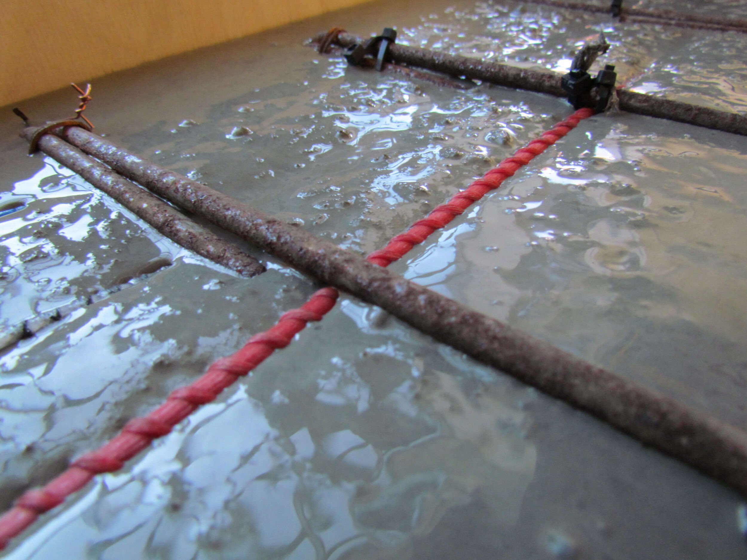
Embedding inside new structures (concrete or soil)
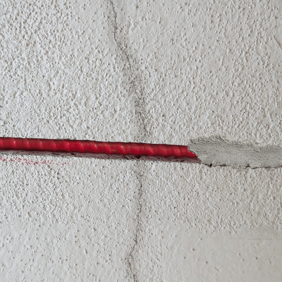
Installation in near-to-surface grooves for existing structures
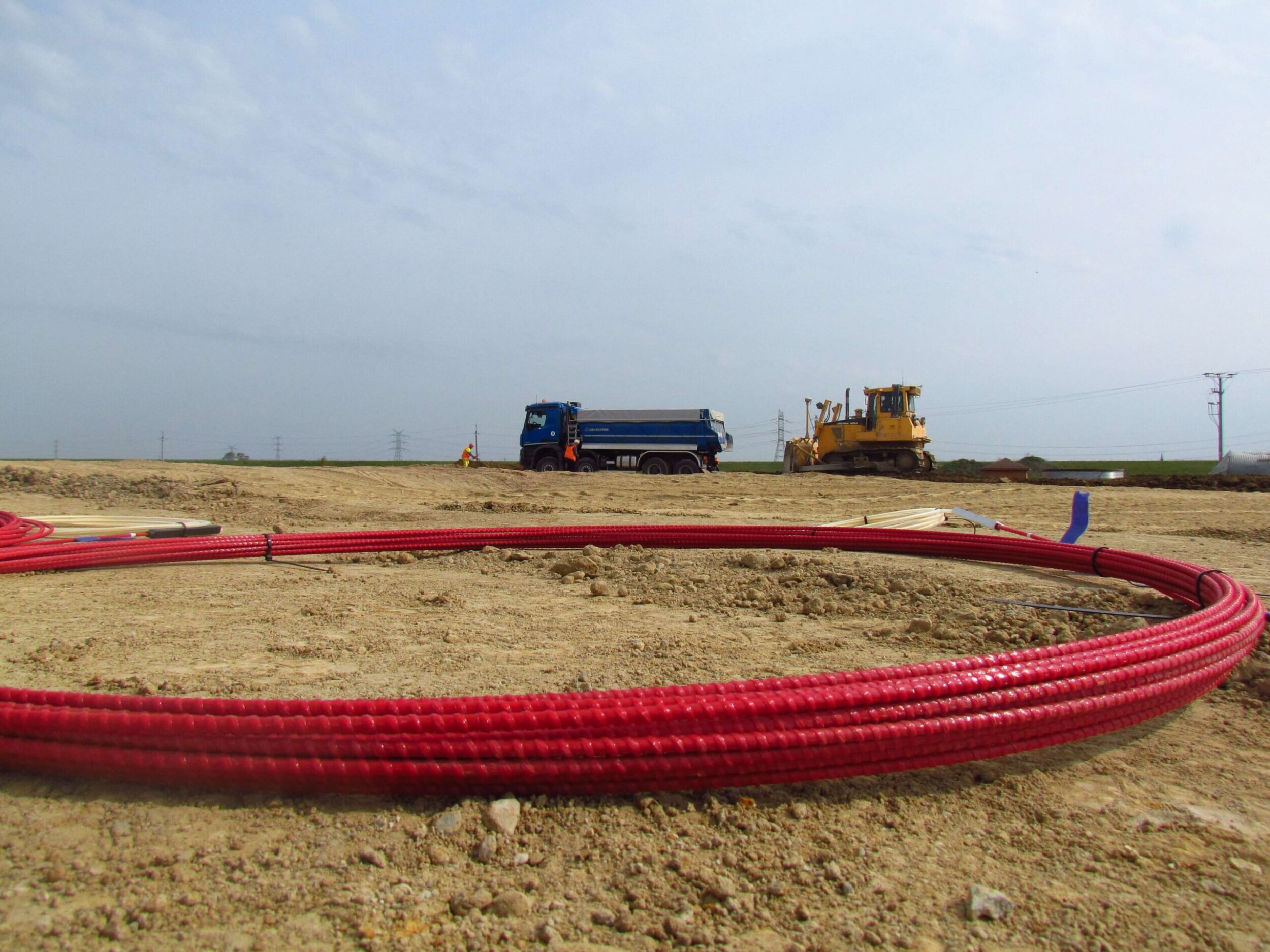
Embedding inside the soil structure
2. Installation in near-to-surface grooves for existing structures. This method requires the preparation of the surface by cutting a grove, the size of which depends on the sensor diameter. It is then filled with a chemical anchor just before mounting the sensor. This method offers similar advantages to embedding.
3. Bonding directly to the sanded, cleaned and degreased structural surface. This approach is relatively simple, but has several drawbacks in terms of durability, resistance and sensitivity to external conditions. It can therefore only be used for short-term measurements with stable thermal conditions. It is also important to choose a suitable adhesive.
Embedding inside new structures (concrete or soil)
Installation in near-to-surface grooves for existing structures
Embedding inside the soil structure
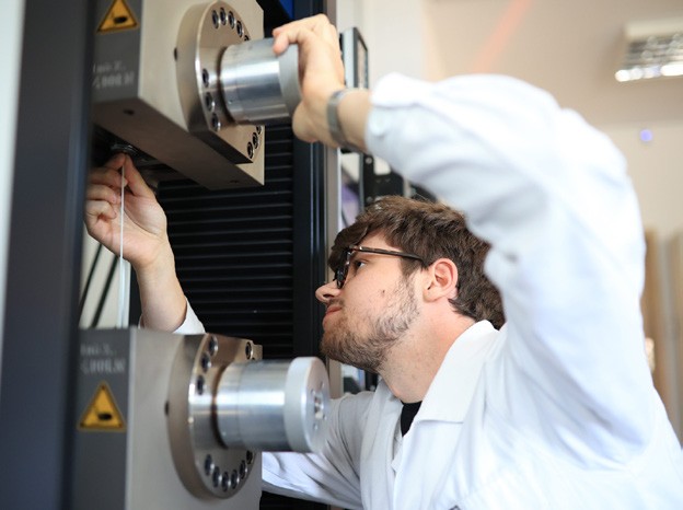
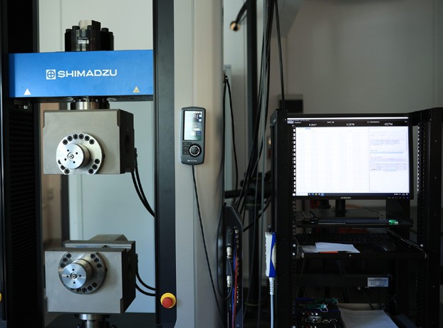
Universal Testing Machine For PDS