
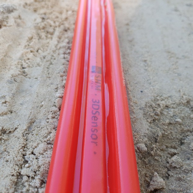
3DSensor
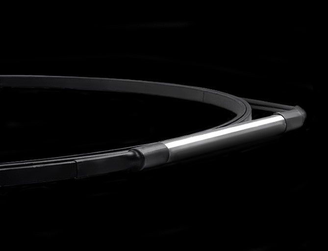
DFOS shape sensor for geotechnical and civil engineering applications that measures displacements in 3D space along its entire length.
The 3DSensor can track curvature profiles and then calculate displacement profiles (in mm) perpendicular to the sensor axis. This feature distinguishes it from all typical axial strain sensing cables and sensors. It is designed to be directly embedded into the monitored structure, for example in a soil embankment, or to be installed on the surface of existing structures.
The 3DSensor can track curvature profiles and then calculate displacement profiles (in mm) perpendicular to the sensor axis. This feature distinguishes it from all typical axial strain sensing cables and sensors. It is designed to be directly embedded into the monitored structure, for example in a soil embankment, or to be installed on the surface of existing structures.

3DSensor Advantages
Physical Quantities Measured
DSS
Strain and crack
Strain and crack
DAS
Vibrations (strain rate)
Vibrations (strain rate)
Typical Materials
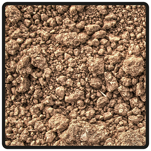
Soil
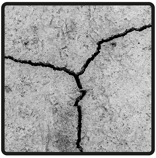
Concrete
Steel
Composite
3DSensor Application Areas
Structures | Bridges | Piles | Slurry walls | Roads | Dams | Embankments | Pipelines | Tunnels | Railways | Earthworks | Geotechnics | Landslides | Minings | Laboratories… and more
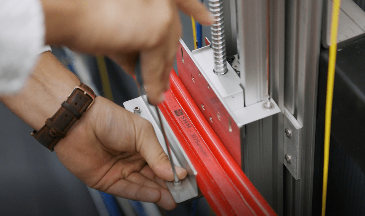
Laboratory research on 3DSensor performance
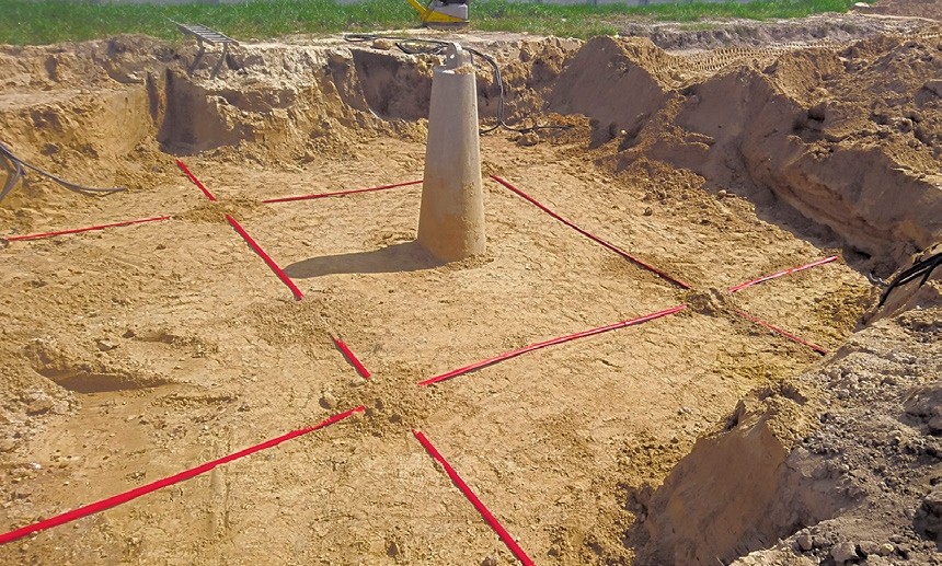
Measurement of a ground vertical displacement – R&D field
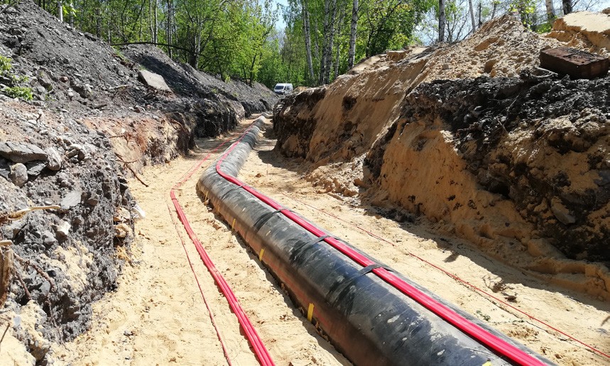
Application of 3DSensor along a gas pipeline
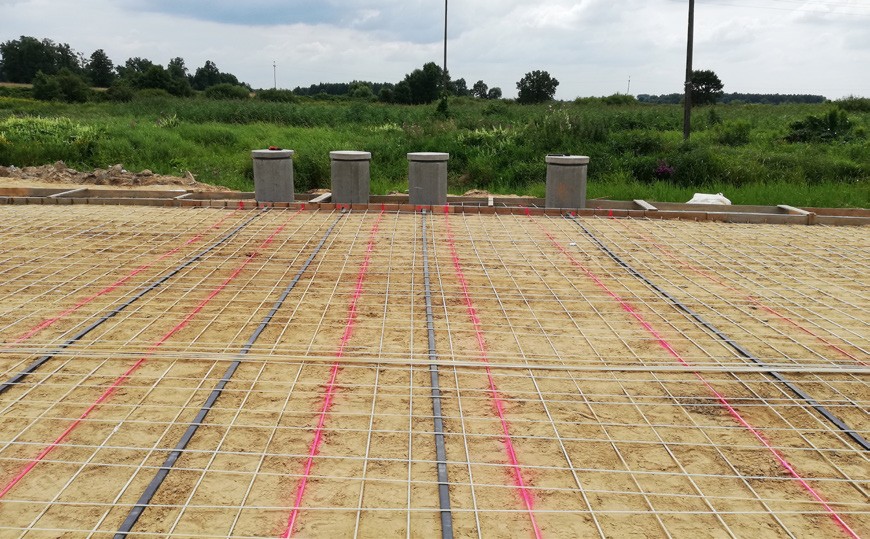
Application of 3DSensor in a road earth embankment
3DSensor Technical Specifications
Displacement resolution1
1 mm
Displacement range2
any, dependent on multiple factors
Elastic modulus
3 GPa
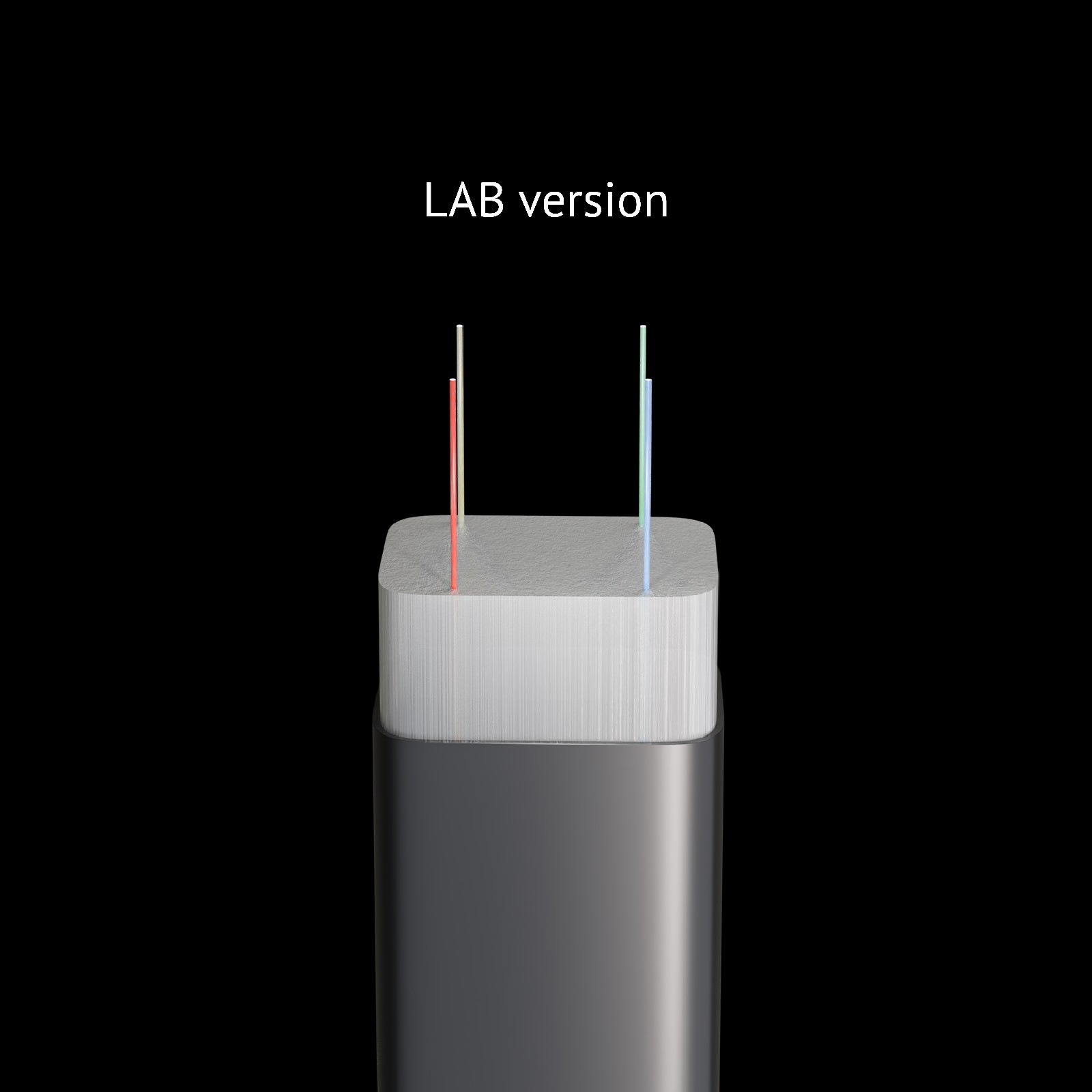
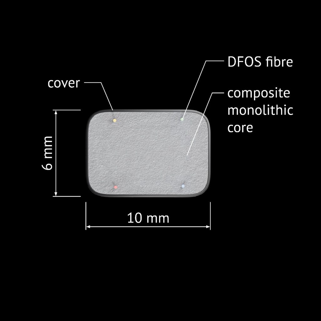
Sensor cross-section3
10 x 6 mm (lab version)
30 x 15 mm (in-situ version)
Bending radius
450 mm (lab version)
450 mm (in-situ version)
Sensor mass
73 kg/km (lab version)
205 kg/km (in-situ version)
Operating temperature4
-20 to +80°C
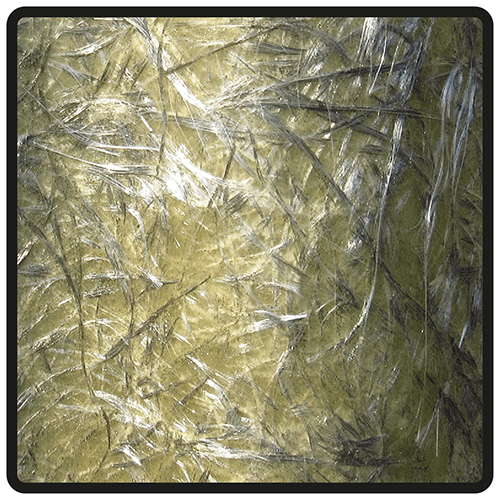
Core material5
PLFRP (polyester fibers + epoxide)
Scattering compatibility
Rayleigh, Brillouin, Raman
Number of sensing fibres6
4
Type of the fibre7
single-mode SMF 9/125
Attenuation8
< 0.3 dB/km
Sensor length9
up to 500 m
1 Typical in sections shorter than 50 m
² Dependent on: sensor’s dimensions (height and width), length, spatial resolution, strain accuracy of the interrogator, boundary conditions and predicted deformation shape (generated strain values). An individual analysis is recommended in each case
3 Standard (other dimensions available on request)
4 Standard (extended temperature range available on request)
5 Standard material (other also available, e.g. polycarbonate)
6 Standard (more fibres available on request); possibility to connect the fibres in a loop
7 Standard (other fibres available on request)
8 At 1550 nm wavelenght
9 Sensors can be connected in series
3DSensor Installation
Each installation should be designed individually, taking into account specific requirements and local conditions.
However, a typical installation in a geotechnical setting involves uncoiling the sensor from a drum, stabilising it on the soil surface using point connectors (e.g. U-shaped), then backfilling and compacting it with a subsequent layer. It is not necessary to ensure perfect adhesion along the length as with the Epsilon strain sensors.
Special attention must be paid to maintaining accuracy and documentation of its position and to avoid twisting the sensor along its axis.
It is also possible to embed the sensor in concrete or bond it along its length to a concrete or steel surface.
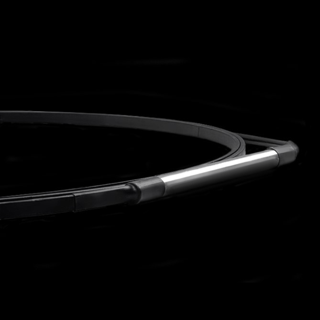
The installation process is facilitated by the fact that the sensor has rectangular cross-section making it easier to lay down or adhere to a flat surface.
Special attention must be paid to maintaining accuracy and documentation of its position and to avoid twisting the sensor along its axis.
It is also possible to embed the sensor in concrete or bond it along its length to a concrete or steel surface.
The installation process is facilitated by the fact that the sensor has rectangular cross-section making it easier to lay down or adhere to a flat surface.
1. Embedding inside new structures (concrete or ground). This approach is best because it ensures optimal bonding properties, natural protection against mechanical damage and direct sunlight influence. It also allows measurements to be taken from a true strain-stress state and offers the best aesthetics (no visible components on the surface).
2. Installation in near-to-surface grooves for existing structures. This method requires the preparation of the surface by cutting a grove, the size of which depends on the sensor diameter. It is then filled with a chemical anchor just before mounting the sensor. This method offers similar advantages to embedding.
3. Bonding directly to the sanded, cleaned and degreased structural surface. This approach is relatively simple, but has several drawbacks in terms of durability, resistance and sensitivity to external conditions. It can therefore only be used for short-term measurements with stable thermal conditions. It is also important to choose a suitable adhesive.
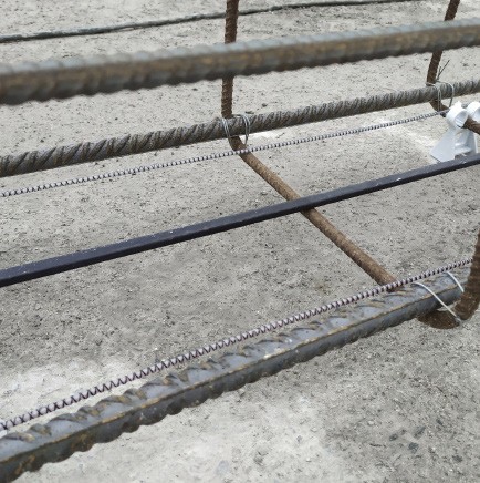
Embedding inside new concrete structure
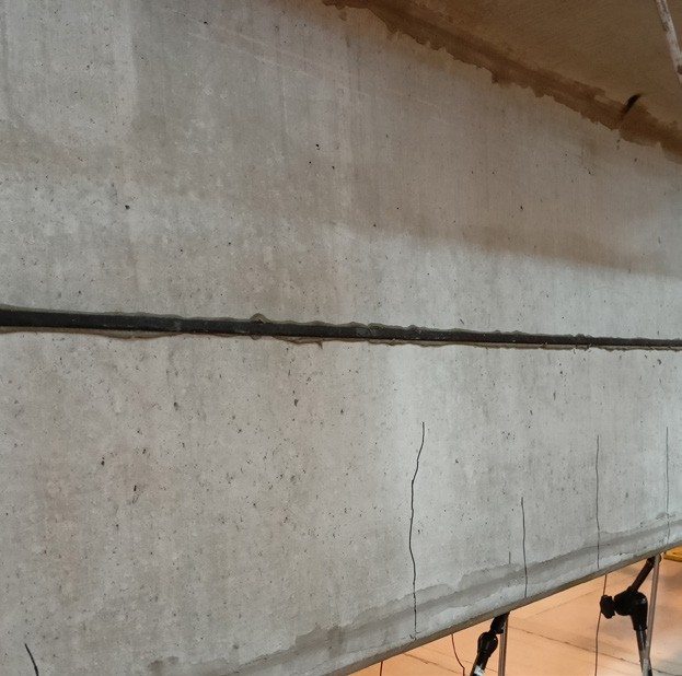
Installation on concrete surface
Embedding inside soil structure
3DSensor FAQ
How does your 3DSensor work?
What is the resolution, accuracy and range of displacements for the 3DSensor?
Can 3DSensor detect displacements in both planes (vertical and horizontal)?
While installing the 3DSensor, what depth would be suitable for burying it, and would it need a sand / free-draining base?
How many fibres are in the displacement 3DSensor?